

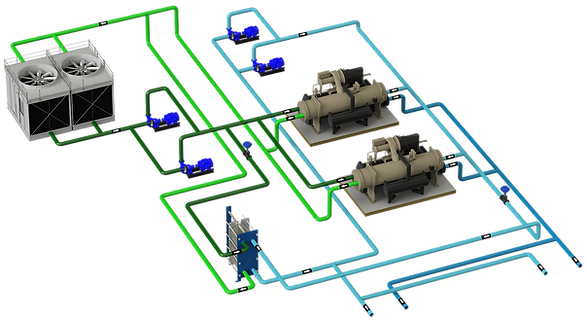
They are the systems that have a decoupling element that separates the primary and the secondary, in such a way that hydraulically what happens in the secondary does not affect the primary.
1 - TECHNICAL SHEET
2 - GENERAL
This is the most typical hydraulic configuration, so much so that it is sometimes applied even without making much sense, such as systems with a chiller.
This hydraulic configuration is normally projected in a system with 2 or more chillers and variable load variation, enough to partialize production by stopping chillers.
It's a very versatile setup setup-wise, not like theconstant flow coupled systemsand especially those ofvariable flow, VPF
The main objective of this configuration is to hydraulically DISCOUPLE the primary from the secondary, that is, that what happens in the secondary does not affect the primary. However, in most cases this does not happen because a shut-off cock or non-return valve is installed in the bypass COUPLING the primary and secondary.
Another common mistake is not paying attention to themanifold connection order,complicating the optimized management of production. Under this situation, in addition to the loss of efficiency, there are problems in the chillers such as an excessive number of starts and stops and an attempt is made to camouflage the problem by adding inertia, which can alleviate the problem but is not solved.
To this day, this configuration with secondary to flow is not recommended due to the low precision that is achieved in the flow temperature and the extra consumption that is had both in secondary pumps, as well as in primary pumps and chillers with Chiller Water. Reset when seeking to alleviate the primary flow defect.
When there is a constant flow, the points to consider in the design and in the control are similar to those indicated in theconstant flow coupled systems, except that now the mixture is produced in the bypass, raising the delivery temperature of the secondary.See more details.

3 - COMBINATION OF CHILLERS
As previously mentioned, this is a very versatile combination in terms of configuration:
-
Flow compatibilities between chillers, here it is not essential that all the chillers that make up the plant are compatible in minimum and maximum flow as a system VPF
-
asymmetric configuration; From a design and control system point of view, an asymmetric configuration does not complicate the system at all. Furthermore, an asymmetric configuration is recommended if it is the best option to match production to demand. In an asymmetric configuration you can have: _cc781905-5-bb36bad5c319-319
-
Base chiller, which will have priority in operation. It could be one with very high efficiency, or heat recovery, or any other reason.
-
Peak chiller, the one that will enter the system last, only when it is really necessary, for example the one with the worst efficiency, or the most deteriorated, etc.
-
Pivoting chiller, the one that is used in the sequencing of chillers both in addition and in subtraction to make the transitions between chillers of greater power.
-
Any of the chillers within the system can take a different role, for example a base chiller with heat recovery and lower efficiency can go to peak when recovery is not needed, or a chiller with integrated freecooling._cc781905-5cde-3194-bb3b -136bad5cf58d_ _cc781905-5cde -3194-bb3b-136bad5cf58d_ _cc781905-5cde-3194-bb3b- 136bad5cf58d_ _cc781905-5cde- 3194-bb3b-136bad5cf58d_ _cc781905-5cde-3194-bb3b-136bad5cf58d _ _cc781905-5cde- 3194-bb3b-136bad5cf58d_
-
-
Symmetrical configuration, in which all the chillers are the same. At this point it is recommended to take into account that the minimum system load is not below the minimum capacity step._d04a07d8-9cd1-3239-8139-6b7d8
4 - CAPACITY MANAGEMENT
In the production control system, in the first place each type of chiller must be considered what role it will play in the order of the sequence, base, peak, pivoting or let's say normal.
If the collector is correctly made and the location of the probes is correct, then an optimized production management can be done, otherwise the system will only be able to do a "simple" sequencing that can present problems in production management.
The control cannot solve the problems that a bad hydraulic design causes, just maybe mask it. Control cannot work miracles.
Addition of chillers:
-
By flow temperature in the collector, under the premise of less number of chillers running as possible. Keep in mind that it is very likely that there is a flow defect in the primary most of the time.
-
By % load, if you want to take a strategy based on partial load curves
Subtraction of chillers, as long as the delivery setpoint condition is met,
-
By AT on the collector, as long as the order of connections is correct
-
By % load in chillers, check before the subtraction that when removing the next chiller in the sequencing that the rest can be done with the demand.
The Chiller Water Reset function to lower the set point temperature of chillers to compensate for the hot water mix in the manifold may be necessary.
The Chiller Water Reset function at cooling temperatureSecondary drive has an energy saving effect.
Adjusting production to demand only in terms of thermal power is a concept that is very fashionable, but by itself it presents deficiencies and might not work if other factors are not taken into account.

Plant control methods:
-
delivery probe
-
return probe
-
bypass probe
-
bypass flow
-
% chiller load
5 - EXCESS OR DEFECT OF PRIMARY FLOW
Why is it necessary to clarify this point?
In this configuration, the secondary is constant and, in the best of cases, variable by steps depending on whether the secondary circuits start or stop.
Let us consider all the secondary constant, the demand only affects the AT being in partial load lower than the design and with a current of hot water circulating through the collector that heats the impulsion.
In this configuration most of the time this circumstance will occur.
The primary flow defect will affect the system as follows:
-
Manifold flow temperature rise
-
Greater number of chillers in operation working at low load to reduce the flow defect
-
Decrease of setpoint temperature in chillers to compensate the mixture

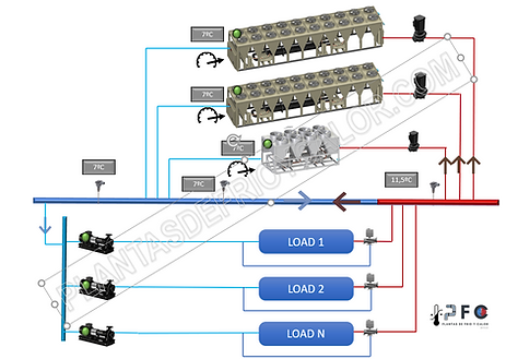
En el secundario se tiene una demanda de 335 KW con un AT de 1ºC. La enfriadora 1 de 500 KW es suficiente para atender la demanda, pero por defecto de caudal en primario la temperatura de impulsión de secundario se eleva hasta 9,4ºC

Para paliar el efecto mezcla, la enfriadora 1 baja su consigna a 5,5ºC, ahora la temperatura de impulsión en el colector es de 7,9ºC

En este ejemplo se añade enfriadora para disminuir el defecto de caudal en primario y no por demanda. Ahora un equipo más grande trabajando a baja carga, y aún así hay elevación de la temperatura de impulsión
En el secundario se tiene una demanda de 335 KW con un AT de 1ºC. La enfriadora 1 de 500 KW es suficiente para atender la demanda, pero por defecto de caudal en primario la temperatura de impulsión de secundario se eleva hasta 9,4ºC
In the images above there are 3 work scenarios, the same plant configuration and the same demand in secondary with an AT 1ºC, but different modes of operation in primary:
-
Scenario 1, the secondary demand is 335 KW with an AT of 1ºC. Chiller 1 is sufficient by capacity to meet the demand, but the flow balance between primary and secondary results in a primary flow defect of 202 m3/h that circulates through the bypass and raises the impulsion temperature to 9.4ºC. Esta temperatura no es válida para la instalación. _cc781905-5cde-3194 -bb3b-136bad5cf58d_ _cc781905 -5cde-3194-bb3b-136bad5cf58d_ _cc781905-5cde-3194- bb3b-136bad5cf58d_ _cc781905- 5cde-3194-bb3b-136bad5cf58d_ _cc781905-5cde -3194-bb3b-136bad5cf58d_ _cc781905-5cde-3194-bb3b- 136bad5cf58d_ _cc781905-5cde- 3194-bb3b-136bad5cf58d_
-
Scenario 2, to compensate for the hot water mix, chiller 1 lowers its setpoint from 7ºC to 5.5ºC with the consequent consumption of extra energy. De esta forma se consigue 7,9ºC _cc781905-5cde-3194-bb3b -136bad5cf58d_ _cc781905-5cde -3194-bb3b-136bad5cf58d_ _cc781905-5cde-3194-bb3b- 136bad5cf58d_ _cc781905-5cde- 3194-bb3b-136bad5cf58d_ _cc781905-5cde-3194-bb3b-136bad5c f58d_ _cc781905-5cde- 3194-bb3b-136bad5cf58d_ _cc781905-5cde-3194 -bb3b-136bad5cf58d_ _cc781905 -5cde-3194-bb3b-136bad5cf58d_
-
Scenario 3, to reduce the primary flow defect, chiller 2 is started, with a higher flow, but working at low load. With this way of working, the chillers must be compatible and with good efficiency at low loads, type inverter or magnetic levitation.
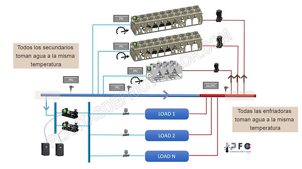
6 - ORDER OF MANIFOLD CONNECTIONS
The order of connections in the manifold is essential in order to achieve an optimized management of the set of chillers.
Many of the problems in existing plants is that the order of connections in the collector is not correct and makes control difficult, so much so that stable operation is not even achieved.
Two simple rules:
-
All chillers drink water at the same temperature
-
All secondaries drink water at the same temperature.
Other aspects in collector designs, such as the diameter, vary depending on how the plant will operate.See more.
7 - DESIGN RECOMMENDATIONS
In a primary and secondary constant flow decoupled type configuration, attention should be paid to the following points:
-
Selection of chillers
-
Pay attention to the operation at partial loads and minimum partialization since it is possible that chillers start up not by demand but by flow.
-
In energy studies, take into account thatchillers in parallel work at the same %of load.
-
-
Chiller Sequencing
-
Addition by flow temperature in collector
-
Addition by % of load if additionally a strategy to work at partial loads is required
-
Subtraction by % load
-
Subtraction by AT collector
-
-
plant configuration
-
Symmetrical configuration (all chillers are the same) or asymmetrical configuration
-
Peak, base, pivoting chillers
-
collector design
-
-
Control of terminal units
-
For de 3-way valve, correctly balance the circuits and terminal units
-