
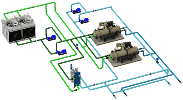
Pumps typically used in HVAC systems are included in this section.
1 - CURVES OF A PUMP
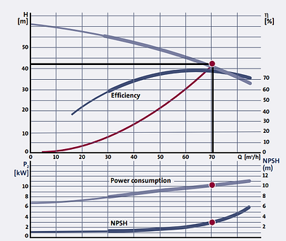
The performance of a centrifugal pump is shown as a set of performance curves. In these, it is represented as a function of flow:
-
the height,
-
consumption,
-
performance and
-
the NPSH
Note: The power and efficiency shown in a curve does not usually include motor power, only pump power, a value known as P2.
Some pumps with built-in motor and drive can refer to the P1 value. In any case, you should always consult.
QH CURVE
It shows the head, expressed in mca (meters of water column) that the pump can give at different flow rates. Giving this value in meters has the advantage that the QH curve is not affected by the type of fluid.see more
This curve overlaps with the curve of the circuit and at the junction point we have the working point of the pump.
The circuit curve indicates that the head loss is proportional to the square of the flow and the ratio of both determines the Kv of the circuit. see more
PERFORMANCE CURVE
It is the ratio between the power that the pump delivers to the water and the power input to the pump, P2.
where:
ρ is the density of the liquid in kg/m3 ,
g is the acceleration due to gravity in m/s2 ,
Q is the flow in m3 /s and
H is the height in m.
For water at 20º C and Q measured in m3 /h and H in m, the hydraulic power Ph in KW, can be calculated as:
Ph = 2.72 x Q x H
Performance depends on pump duty point. It is important to select a pump that matches the flow requirements and ensures that the pump works in the most efficient flow area.

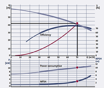


P2 CONSUMPTION CURVE
The consumption of the pump increases as the flow rate increases.
NPSH (Net Positive Suction Head)
It is the minimum absolute pressure that must be on the suction side to avoid cavitation. It is measured in meters and depends on the flow see more


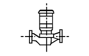
2 - TYPES OF PUMPS, INLINE AND END SUCTION
In HVAC systems, the most commonly used pumps are:
-
Inline pumps, single stage close coupled
-
Single-stage end-suction pumps, both close and long coupled
Pump definitions:
-
End Suction Pump = Fluid goes directly to the impeller. The inlet and outlet have a 90° angle.
-
In-line pump = Liquid passes directly through the in-line pump. Suction pipe and discharge pipe are placed facing each other and can be mounted directly in the piping system
-
Split chamber pumps= Pump with longitudinally divided housing.
-
Horizontal pump = Pump with the axis horizontal
-
Vertical pump = Pump with vertical shaft
-
Single cell pump = Pump with a single impeller.
-
Multicell pump = Pump with several cells coupled in series.
-
Long-Coupled Pump = Pump connected to the motor by a flexible coupling. The motor and pump have separate bearing structures.
-
Close coupled pump = Pump connected to the motor via a rigid coupling.

3 - INSTALLATION OF PUMPS
In the Grundfos manual, there is the following summary of the positions of the pumps depending on the location and the type of pump:

Regarding the valves that the pump must have:
-
Aspiration
-
Cutting key
-
Filter
-
anti vibration sleeve
-
eccentric reduction
-
Manometer [*]
-
-
Download:
-
Concentric reduction
-
Non-return or retention valve
-
Depending on the diameter and to avoid water hammer, the use of [**] is recommended
-
Flapper, recommended for diameters less than DN32
-
Disc or split disc non-return valves, with return spring, for diameters less than DN 150
-
Motorized or disc for diameters greater than DN150
-
-
-
Cutting key
-
Manómetro [*] _cc781905 -5cde-3194-bb3b-136bad5cf58d_ _cc781905-5cde-3194- bb3b-136bad5cf58d_ _cc781905- 5cde-3194-bb3b-136bad5cf58d_ _cc781905-5cde-3194-bb3b -136bad5cf58d_ _cc781905-5c de-3194-bb3b-136bad5cf58d_ _cc781905-5cde-3194-bb3b -136bad5cf58d_ _cc781905-5cde -3194-bb3b-136bad5cf58d_ _cc781905-5cde-3194-bb3b- 136bad5cf58d_ _cc781905-5cde- 3194-bb3b-136bad5cf58d_ _cc781905-5cde-3194-bb3b-136bad5cf58d _ _cc781905-5cde- 3194-bb3b-136bad5cf58d_ _cc781905-5cde-3194 -bb3b-136bad5cf58d_ _cc781905 -5cde-3194-bb3b-136bad5cf58d_
-
-
[**] For RITE projects, the recommendation passes to compliance with la IT 1.3.4.2.7 Water hammer
-
[*] Between the suction and discharge of the pump, a set of manometers must be installed to check the height difference. It is recommended that it be a differential set, since with the wrench set it is possible to read the suction and discharge pressure and the difference with a single pressure gauge.

In the upper figure, the typical connection diagram of pump components is represented.
The figure on the right details the 2 ways of installing pressure gauges in a pump.
Plantasdefrioycalor.com recommends the second installation, a manometric bridge, since it allows the measurement of differential pressure, and with a single meter that otherwise could have different settings.
In open systems, the suction pressure gauge usually reads 0 unless the liquid column is greater than atmospheric pressure + suction pressure.
In any case, the installation of pressure gauges must include a swivel or commonly known as a "pig's tail".

When there is a tandem of pumps in parallel, the connection shown in the lower illustration is recommended, so the system is balanced.
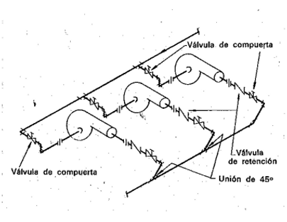
When connecting the pumps, the accumulation of air bubbles must be avoided as much as possible (See NPSH). The following figure shows pump suction connection recommendations.

4 - HEIGHT VS PRESSURE
Pumping head and pumping pressure are two different terms although they are sometimes used interchangeably.
The height of a pump is a way of expressing how high the pump can lift a liquid.
The height is measured in meters (m) and is independent of the density of the liquid.
The following formula shows the relationship between pressure (p) and height (H):
H = p / ρxg
where :
-
H is the height in [m]
-
p is the pressure in [Pa = N/m2 ]
-
ρ is the density of the liquid in [kg/m3 ]
-
g is the acceleration due to gravity in [m/s2 ]
Normally, the pressure p is measured in [bars] (1 bar = 10^5 Pa. although there are other units of measurement.
The following graph visually shows the pumping head of different fluids for the same pumping pressure:

5-NPSH
The NPSH is another of the values that define the characteristics of a pump, from the English "net positive suction head" and is defined as the difference between the inlet pressure and the lowest pressure level inside the pump.
A pumping system has an NPSH that is simply defined as the absolute pressure available at the pump inlet Pe (suction port) minus the saturation pressure corresponding to the fluid temperature Ps and is called available NPSH (NPSHd). :
NPSHd = Pe - Ps
The NPSH value indicates to what degree the pump is not capable of creating an absolute vacuum, that is, raising a column of water 10.33 m above sea level.
NPSH can be referred to as NPSHr (required) or NPSHa (available).
-
Required NPSH is the required suction head for the pump
-
Available NPSH is the suction head available in the system
Not taking into account the NPSH of the pump and the installation can lead to cavitation phenomena. The most obvious manifestations of cavitation in a pump are noise and vibrations followed by loss of flow or, in severe cases, destruction of the pump impeller.

6 - LAWS OF AFFINITY
The affinity laws of a centrifugal pump allow us to calculate working points in different conditions from others:
-
The flow varies proportionally with the rotation speed
-
The pressure varies with the square of the speed of rotation.
-
Consumption varies with the cube of the rotation speed
Affinity laws are useful for estimating pump performance at different speeds or impeller diameters D, based on a pump with known characteristics. The following two variations can be analyzed using these relationships:
-
By changing the speed and keeping the diameter of the impeller constant, the performance of the pump remains the same, but the pressure, capacity and power vary according to the laws of affinity.
-
By changing the diameter of the impeller and keeping the speed constant, the performance of a pump is not affected if the diameter of the impeller is changed by less than 5%. However, performance changes if the impeller size is reduced enough to affect the clearance between the casing and the periphery of the impeller.
The affinity laws assume that the system curve is known and that the pressure varies as the square of the flow rate. The operating point is the intersection of the total system curve and the pump curve.
Since the affinity law is used to calculate a new condition due to a change in flow or pressure (for example, reduction in pump speed or impeller diameter), this new condition also follows the same system curve. Figure 25 shows the relationship of flow, pressure and power expressed by the affinity laws.


7 - PUMPS IN SERIES AND PARALLEL
In HVAC systems it is common to see tandem pumps in parallel to meet flow requirements, and to a lesser extent in series (at least voluntarily).see more.
7.1 Pumps in parallel
When pumps are used in parallel:
-
The required flow rate is higher than that of the available pump
-
The system can vary the flow by starting and stopping pumps
When the pumps are installed in parallel, they each operate at the same pressure and provide their share of the system flow at that pressure. In other words, to create the resulting curve, the flow rates of each pump that makes up the set are added to each pressure. In the image below it can be seen that for pressure 1, the resulting flow is X + X and for pressure 2, Y + Y.
-
Note: In the event that the pumps have different curves with different pressures, there will be work zones in which only 1 of the pumps can contribute:


It is recommended that the pumps be the same since facilitates the calculation and operation, although they may be different or even the same but some with a frequency inverter (so by varying its curve it would be like a different pump) .
When you have several pumps in a manifold and you have variable flow, you have the option of placing drives in all the pumps or only in one of them, each option has its advantages and disadvantages:
-
Drive only on one pump:
-
✅ Initial investment cost
-
❌ The flow regulation is not optimal, when the pump without a drive is running and the second pump with a drive starts, depending on the system curve, it can even reach 100% rotation speed without having an impact.
-
❌ It is not possible to optimize the set and search for the maximum efficiency working point of the running pumps.
-
-
Variator on all pumps:
-
✅ Allows more precise flow regulation
-
✅ Allows you to optimize the performance of the set
-
❌ Initial investment cost
-
When there are pumps in parallel, it is necessary to place elements to avoid the recirculation of one over the other, as mentionedhigher.
7.2 Pumps in series
This configuration is used when it is required to raise the pumping pressure of the system.
‼️ It must be remembered that serial pumps do not add flows, they add pressures, and the resulting flow is dominated by the pump with the lowest flow.
It is less common to find this configuration in HVAC systems since it does not require so much pressure that it cannot be supplied with a single pump.
When the pumps are applied in series, each pump operates at the same flow rate and provides its share of the total pressure at that flow rate. That is, to build the resulting curve, the pressure is added to each flow, if the pumps are the same, it is doubled. In the graph below, for a Q1 flow the pressure is X + X and for a Q2 flow, Y + Y.


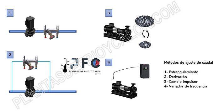
8 - PUMP FLOW ADJUSTMENT
Once the pump is installed and started up and if the flow rate is higher than that required by the system, the working point must be adjusted.
There are several ways:
-
Throttling, is based on the installation of a flow regulation valve in series. Its operation is to generate an additional load loss in the circuit and reduce the flow rate.
-
✅ Simple installation, initial cost, regulation
-
❌ Energy consumption that is dissipated by the HP of the valve, is a lost pumping energy _cc781905-5cde-3194-bb3b-136bad5cf58d-5cc58d0_ 3194-bb3b-136bad5cf58d_
-
-
Bypass control, now the regulating valve is installed in parallel with the pump and acts as if it were a pump with a lower maximum head and a more linear than quadratic curve.
-
✅ Simple installation, initial cost, regulation
-
❌ Greater pumping consumption, since despite reducing the head, the total pumping flow is higher. _cc781905-5cde-3194-bb3b-136bad5 _cc781905-5cde-3194 -bb3b-136bad5cf58d_ _cc781905 -5cde-3194-bb3b-136bad5cf58d_ _cc781905-5cde-3194- bb3b-136bad5cf58d_ _ cc781905-5cde-3194-bb3b-136bad5cf58d_ _cc781905-5cde-3194 -bb3b-136bad5cf58d_ _cc781905 -5cde-3194-bb3b-136bad5cf58d_ _cc781905-5cde-3194- bb3b-136bad5cf58d_ _cc781905- 5cde-3194-bb3b-136bad5cf58d_ _cc781905-5cde-3194-bb3b-1 36bad5cf58d_ _cc781905-5cde- 3194-bb3b-136bad5cf58d_ _cc781905-5cde-3194 -bb3b-136bad5cf58d_ _cc781905 -5cde-3194-bb3b-136bad5cf58d_ _cc781905-5c de-3194-bb3b-136bad5cf58d_ _cc781905-5cde-3194-bb3b -136bad5cf58d_
-
-
Change of the impeller diameter, when the flow deviation is very high and therefore requires a high setting. A parallel curve is generated according to the laffinity eyes.
-
✅ Reduction of pumping consumption
-
❌ It does not allow continuous regulation, that is, once the impeller is changed, the pump work curve is modified. _cc781905-5cde-3194-bb3b-136bad5cf58d _cc781905-5cde-3194 -bb3b-136bad5cf58d_ _cc781905 -5cde-3194-bb3b-136bad5cf58d_ _cc781905-5cde-3194- bb3b-136bad5cf58d_ _cc781905-5cde-3194-bb3b-1 36bad5cf58d_ _cc781905-5cde- 3194-bb3b-136bad5cf58d_ _cc781905-5cde-3194 -bb3b-136bad5cf58d_ _cc781905 -5cde-3194-bb3b-136bad5cf58d_ _cc781905-5c de-3194-bb3b-136bad5cf58d_ _cc781905-5cde-3194-bb3b -136bad5cf58d_ _cc781905-5cde -3194-bb3b-136bad5cf58d_ _cc781905-5cde-3194-bb3b- 136bad5cf58d_ _cc781905-5cde- 3194-bb3b-136bad5cf58d_ _cc781905-5cde-3194-bb3b-136bad5cf58d _ _cc781905-5cde- 3194-bb3b-136bad5cf58d_ _cc781905-5cde-3194 -bb3b-136bad5cf58d_ _cc781905 -5cde-3194-bb3b-136bad5cf58d_ _cc781905-5cde-3194-bb3 b-136bad5cf58d_
-
-
Speed control with frequency inverter (or pumps with EC motors)
-
✅ Reduction of pumping consumption and continuous regulation according to regulation (by AT, constant AP or compensated AP)
-
✅ Increase the pumping flow by increasing the rotation speed by increasing Hz
-
❌ Initial investment cost, although it is not currently very high.
-