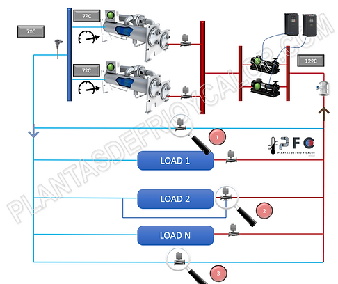

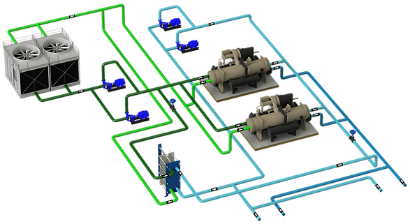
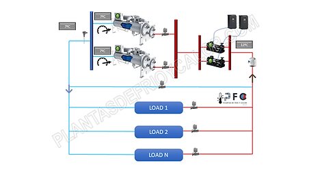
These are the systems that the same pump or group of pumps move the water through the generators and through the rest of the installation to the terminal units.
The distribution is variable flow
1 - TECHNICAL SHEET
01
When
-
Systems with several chillers
-
Systems with load variation
-
variable flow
-
Regulation in terminal units with V2V.
-
Plant operator with technical knowledge
02
Advantages
-
Maximum energy savings en pumping, everything is variable
-
Low initial investment cost, compared to decoupled systems
-
stable temperature
03
Drawbacks
-
Rigid system in configuration, it requires a good study of the configuration and the compatibility between chillers.
-
Robust control system, complex manual operation
-
Initial investment in certain field elements
04
Control
-
sequencing planning
-
Addition and subtraction by temperature
-
Addition and subtraction by flow, it is important to monitor the minimum and maximum flow
-
Addition and subtraction %load
-
Pump sequencing and rotation speed variation
-
Differential pressure probe location
-
Flow measurement
-
Bypass flow control. The selection of the diameter and type of V2V is crucial
05
To consider
-
Better chillers of the same capacity and AP evaporator, greatly simplifies hydraulic design and control
-
Chiller compatibility (minimum and maximum flow, also known as TD Turn down ratio)
-
Chillers with flow rate variation of at least 50% over nominal
-
Check configuration in sidecar if necessary
-
Dedicated pump vs. tandem pumps
-
V2V Isolation of chillers
-
Element sequencing time > Download at start
-
-
Correct selection of V2V in the terminal units, can determine the success or failure of the system. See selection of V2V
-
sum of resistors in series vs parallel
-
Balancing valve in chillers
6 - BY-PASS VALVE
Another differentiating element of a VPF system and which is vital to ensure the success of the system.
Its function is to open the by-pass modulatingly to ensure that it does not operate below the minimum flow rate of the chillers.
It is a valve that can be subjected to the highest differential pressure in the system if it is located in the header.
Therefore, it must be capable of modulating throughout its operating range in all circumstances.
For what flow? A common mistake is to think that it is sized for the flow of one of the chillers.
Where it is located? Three common options:
-
Close to the discharge of chillers and suction of pumps, which presents the greatest energy savings, but requires a valve capable of operating at high pressure. With this location, if the system requires chilled water quickly and there is no circulation through the distribution circuit, there could be a delay.
-
3-way valve in some terminal units, simplifies the operation and the response time in receiving cold water, but against it there is an overconsumption and oversizing of the pumping system.
-
Locate the 2-way valve at the end of the circuit, with the advantage that the valve is subjected to less pressure and helps modulation, but there will be higher pumping costs due to subjecting the circuit to higher pressure during operation.